open image in lightbox

I-Device Communication Setup in TIA Portal

This blog article explains how to set up I-Device communication between PLCs in TIA Portal. The instructions are based on TIA Portal V19.

I-Device communication enables the exchange of signals between two PLCs, including standard and safety-related signals. The connection is always established between two controllers: one PLC acts as the IO controller, while the other operates as the IO device.

In this article, we cover two common scenarios:

  1. Both PLCs are part of the same TIA Portal project.

  2. Each PLC is configured in a separate TIA Portal project.

If you are using a communication module (CM), the procedures described in this article apply in the same way.
1. Two PLCs in the Same Project

1.1. Setup

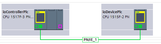
Starting point: Both PLCs are part of the hardware configuration in the same TIA Portal project and belong to the same PROFINET IO system.

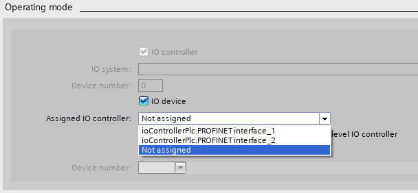
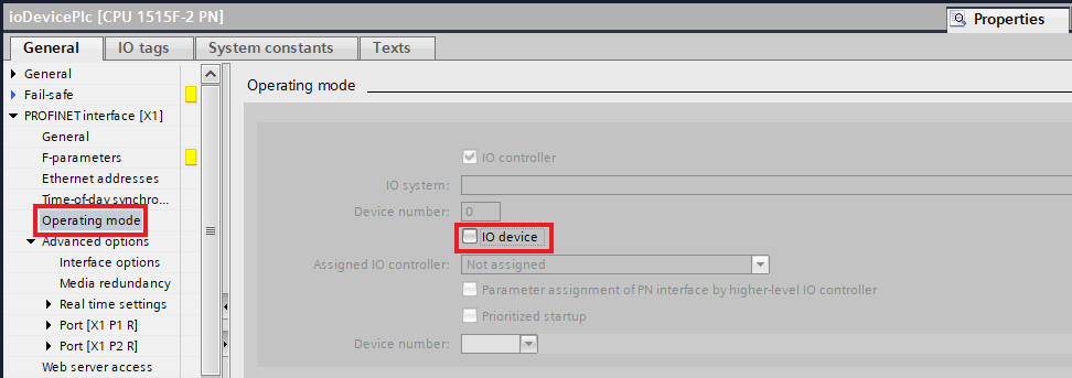
Open the properties of the PROFINET (PN) interface on the device PLC. Under Operating mode, enable the IO device option and then assign the corresponding IO controller.

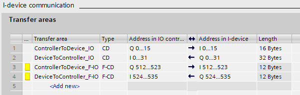
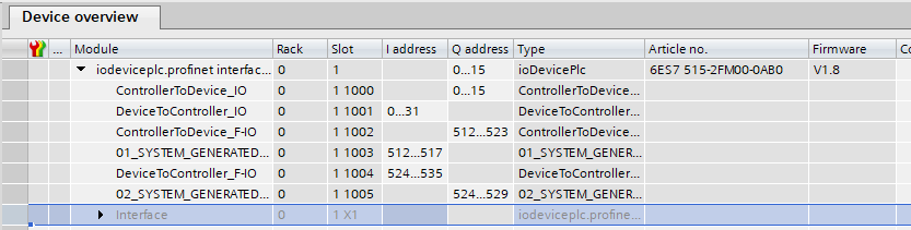
Next, create the required transfer areas. Each transfer area defines a set of signals that are transferred in a single direction. The Type can be either CD or F-CD:

  • CD is used for standard signals.

  • F-CD is used for safety-related signals.

For standard signals, the length of the transfer area can be configured freely, up to the maximum length supported by the PLC. Safety transfer areas always have a fixed lenght of 12 bytes. Of these, 6 bytes are reserved for safety communication, leaving 6 bytes available for user data.

If the maximum length of a single transfer area is not sufficient, you can create additional transfer areas.

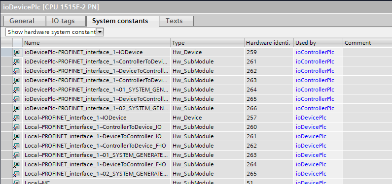
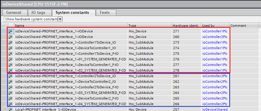
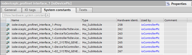
Once the transfer areas have been configured, two system constants are created for each transfer area—one set for the IO controller and one for the IO device. These constants can be found on the System constants page in the properties of the device PLC.

1.2 Signals

Standard signals can be accessed by creating IO tags. If the signals are organized in a user-defined data type (UDT), you can also use the DPRD_DAT and DPWR_DAT functions together with the generated hardware identifiers.

Safety signals must be accessed in the safety program using the RCVDP and SNDDP functions. These functions require the generated hardware identifiers as well as an unique DP_DP_ID, you have to create.

The data structure supported by these blocks is fixed to 6 bytes and consists of 16 BOOL values plus either 2 INTs or 1 DINT.

1.3 Shared Device

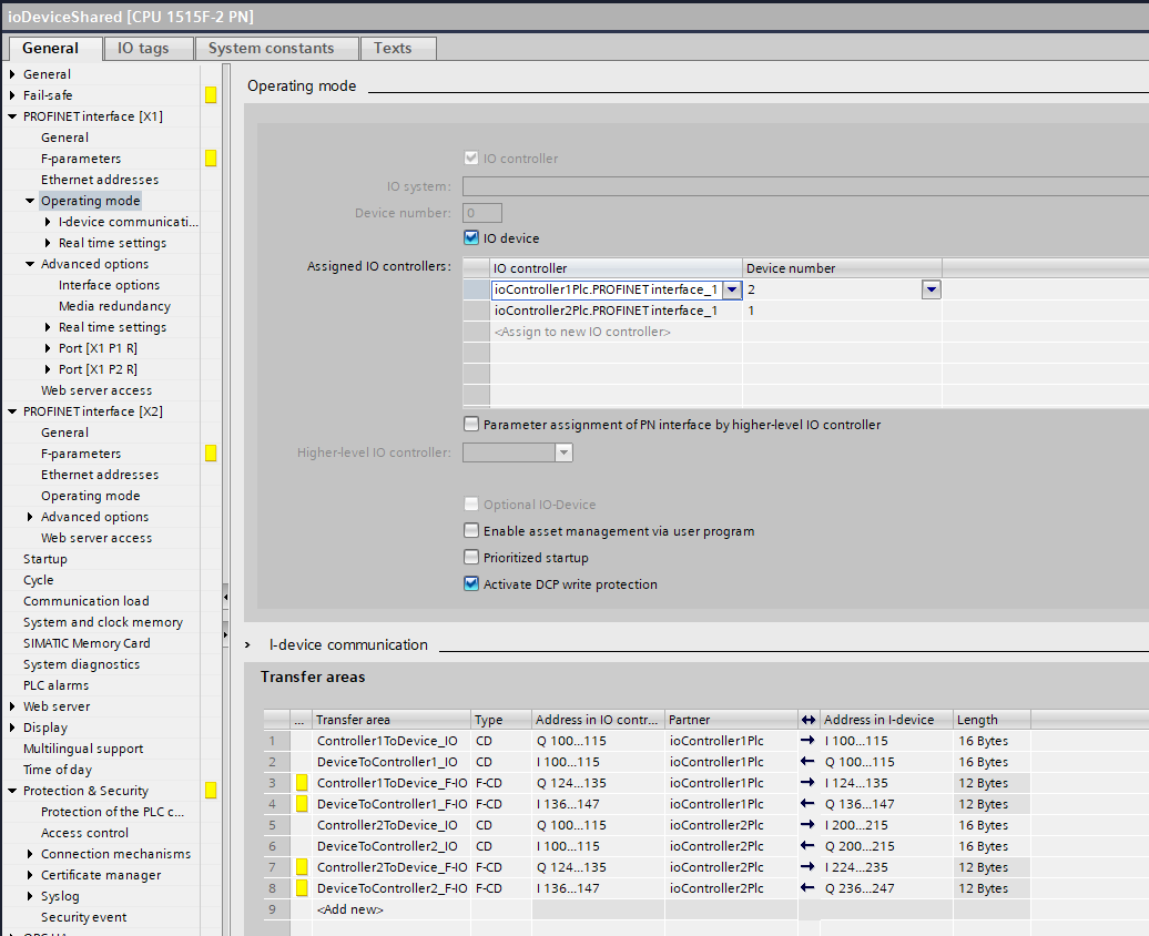
You can also set up the IO device as a shared device. In this configuration, multiple IO controllers can communicate with the same IO device. For each transfer area, you can individually define which IO controller is responsible for the communication.

To configure a shared device, first add an additional IO controller in the Operating mode settings of the IO device PLC. Then, when creating the transfer areas, select the desired partner for each transfer area to specify the corresponding IO controller.

The configured transfer areas are available only to the assigned IO controller. The created system constants are also assigned to their respective controllers.

Each IO controller accesses its assigned transfer areas in the same way as it would with a dedicated (non-shared) IO device.

2. PLCs in Separate Projects

2.1 IO Device PLC

First, add a PLC to your project that matches the IO controller PLC. Make sure that it has the same device type, firmware version, and PROFINET device name on the interface that will be used for the connection.

Next, enable the IO device operating mode on the device PLC, assign the IO controller, and configure the transfer areas as described in Section 1.1.

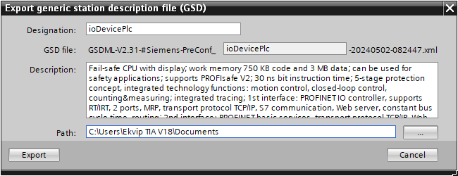
Once the configuration is complete, generate a GSD file from the device PLC. The corresponding button is located below the transfer area configuration.

2.2 IO Controller PLC

Install the GSD file generated from the IO device PLC.

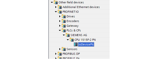
After the installation, the IO device PLC will be available in the hardware catalog under Other field devices > PROFINET IO > PLCs & CPs.

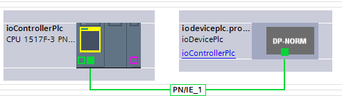
Drag and drop the device into your project and connect its PROFINET interface to the IO controller PLC.

The IO addresses can be configured in the Device view. They do not have to match the addresses configured for the transfer areas on the IO device PLC.

TIA Portal automatically generates the corresponding system constants for the configured transfer areas.

2.3 Signals

Standard signals can be accessed by creating IO tags. If the signals are organized in a user-defined data type (UDT), you can also use the DPRD_DAT and DPWR_DAT functions together with the generated hardware identifiers.

To send or receive safety signals, you will need to use the RCVDP/SNDDP functions in the safe program with the generated hardware identifiers and a unique DP_DP_ID that you have created.

The data structure transmitted by these blocks is also limited: It always consists of 16 BOOL values and either 2 INTs or 1 DINT (6 bytes in total).

2.4 Shared Device

To use a Shared Device across multiple TIA Portal projects, first configure it as described in Sections 1.3 and 2.1. In the IO device PLC project, you must create an IO controller PLC for each controller that will communicate with the Shared Device.

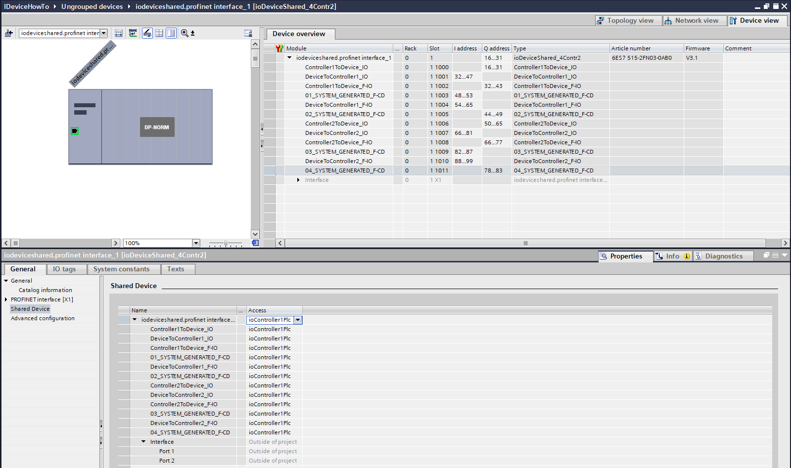
The generated GSD file always contains all configured transfer areas. After importing the GSD file into an IO controller project, the IO device will appear as shown below.

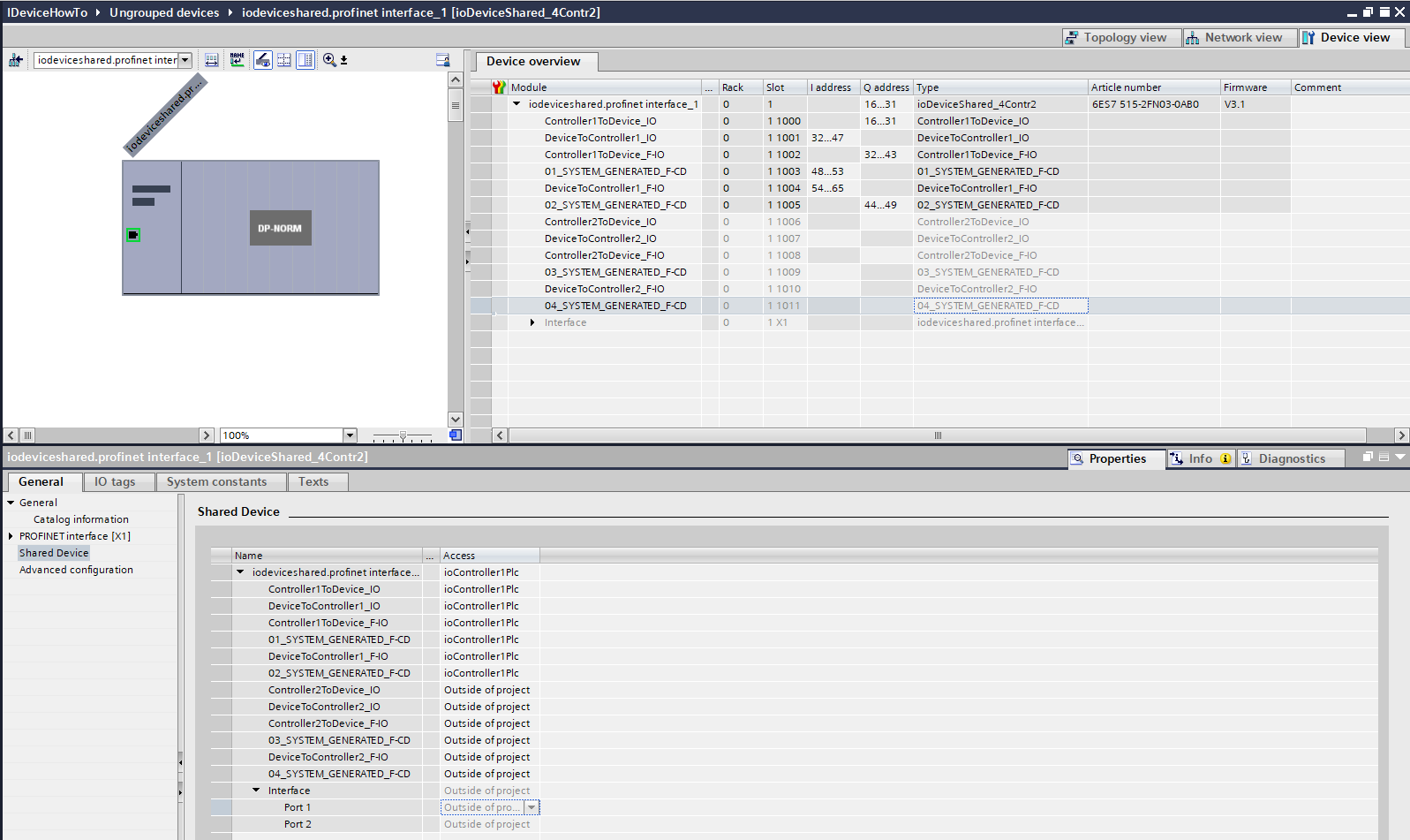
In the properties of the IO device, open the Shared Device page. Here, configure which transfer areas are used by the current IO controller. Set all transfer areas that are not required in this project to Outside of project. Only the transfer areas assigned to the current IO controller will then be available.

To ensure that the Shared Device operates correctly, all projects must use the same GSD file. In addition, each transfer area must be assigned to only one IO controller. A transfer area must never be accessed by multiple IO controllers at the same time.

The signals of the configured transfer areas can then be accessed in the same way as for a dedicated (non-shared) IO device.