open image in lightbox

Initial drive commissioning in TIA Portal as a technology object (TO)

Introduction

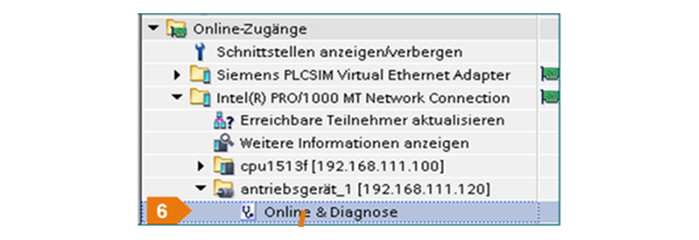
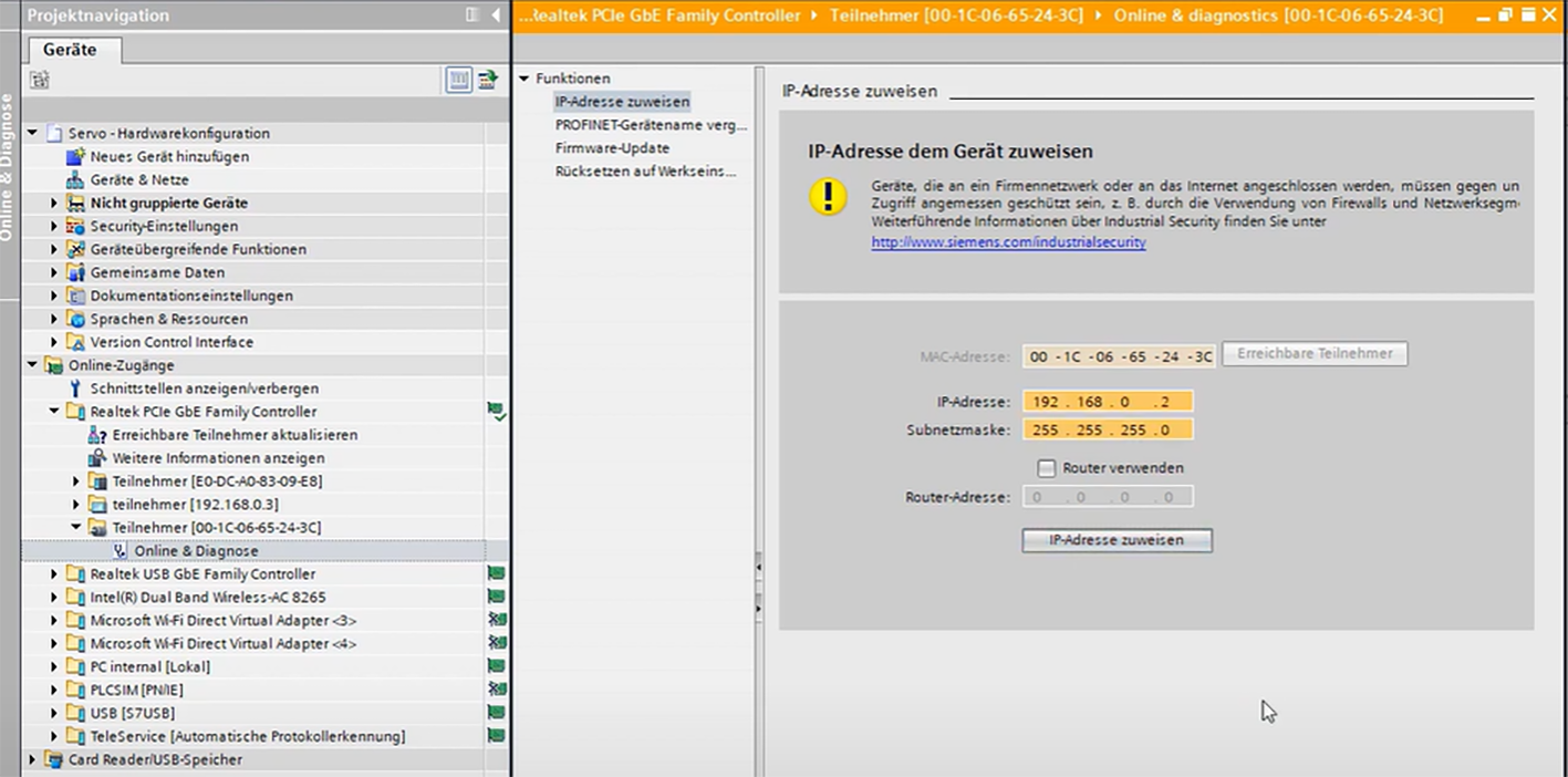
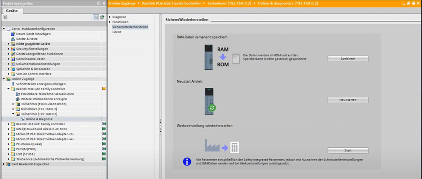
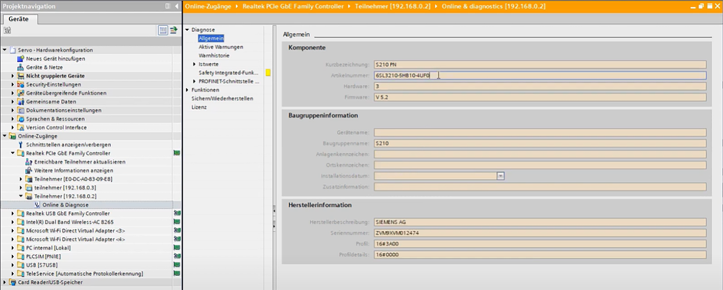
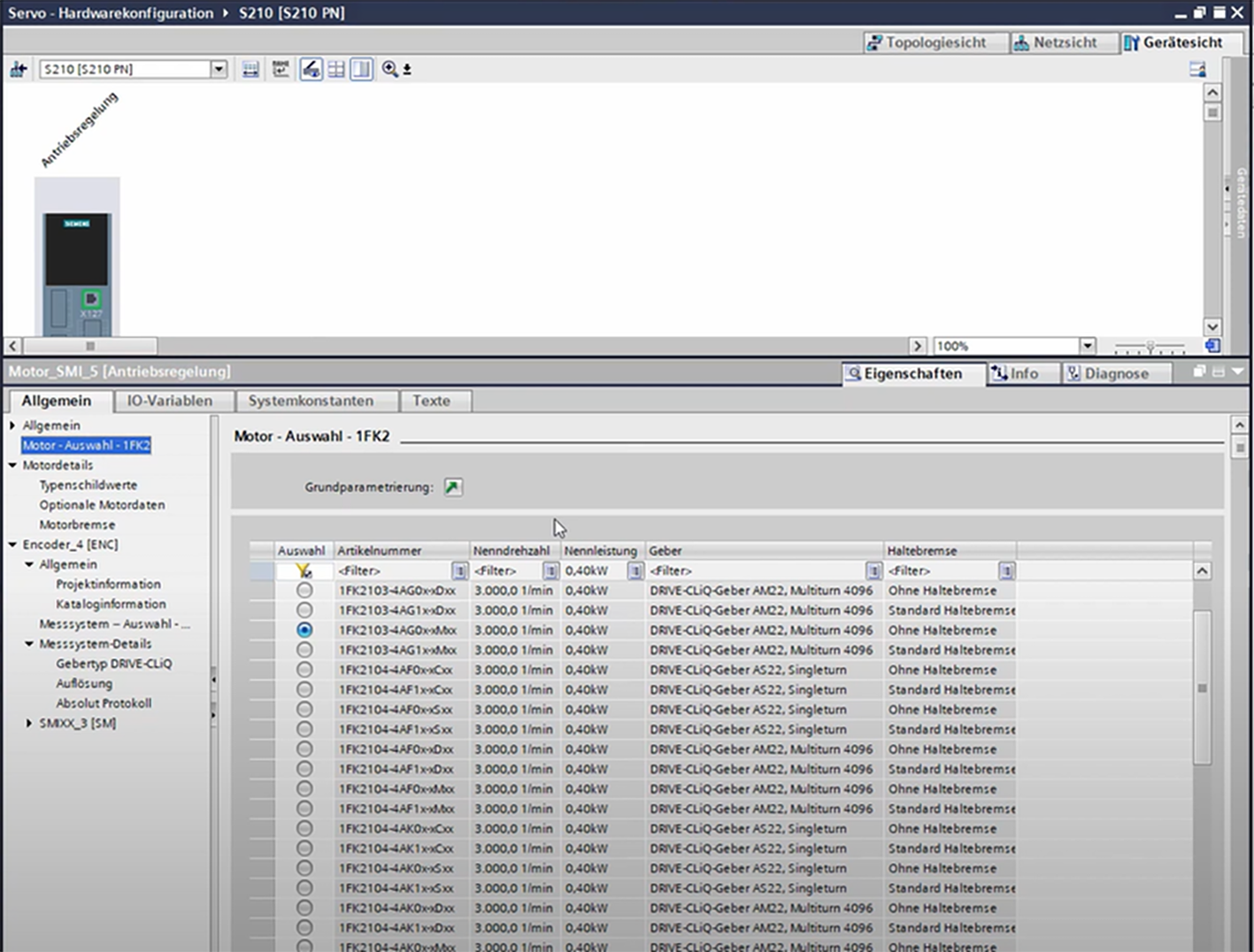
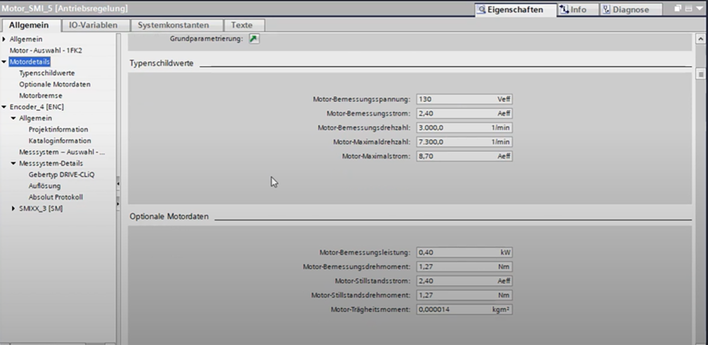
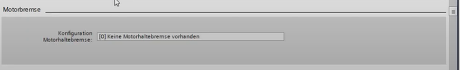
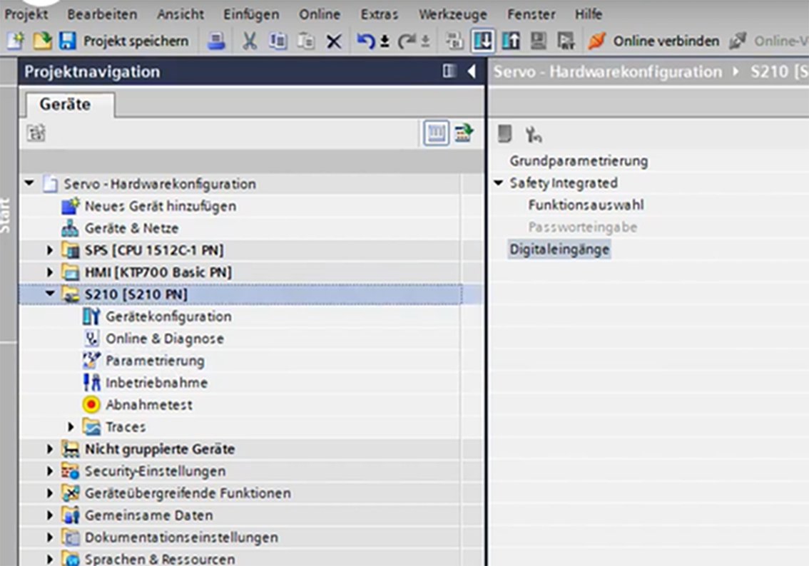
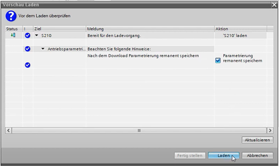
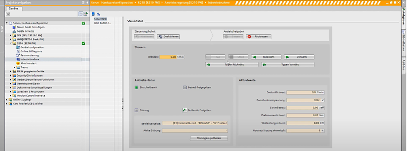
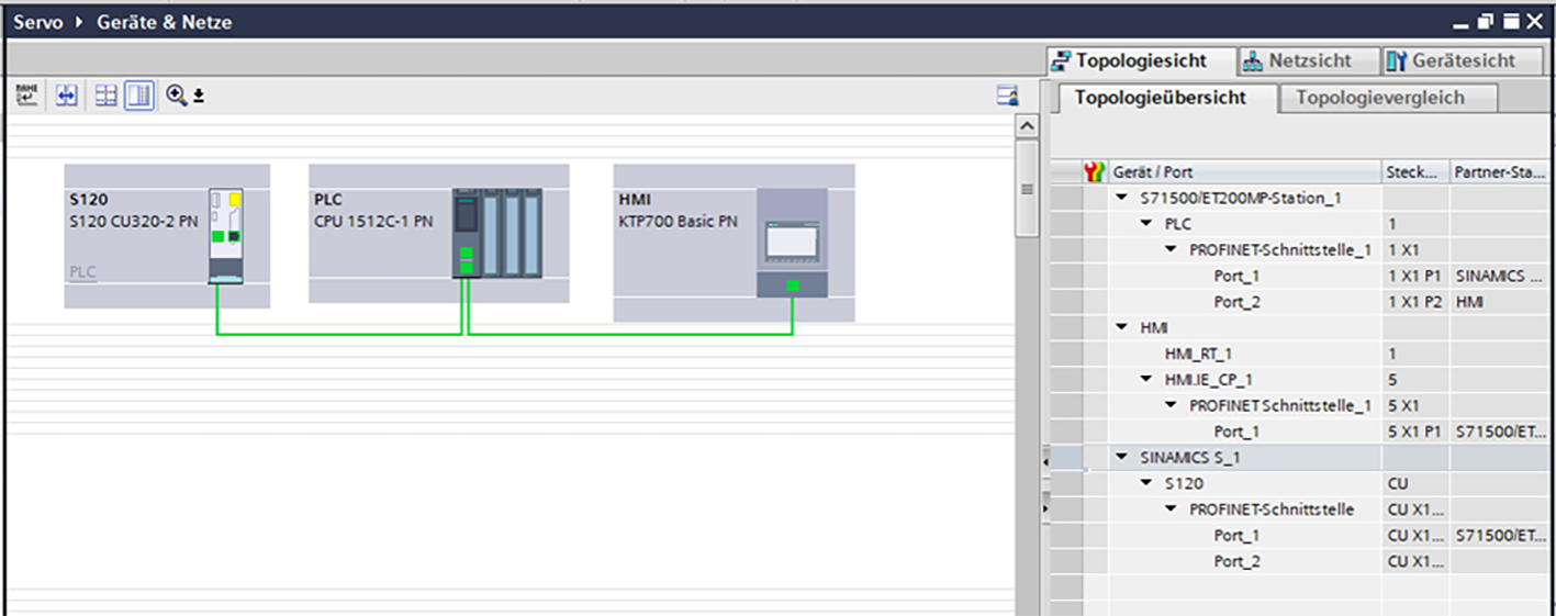
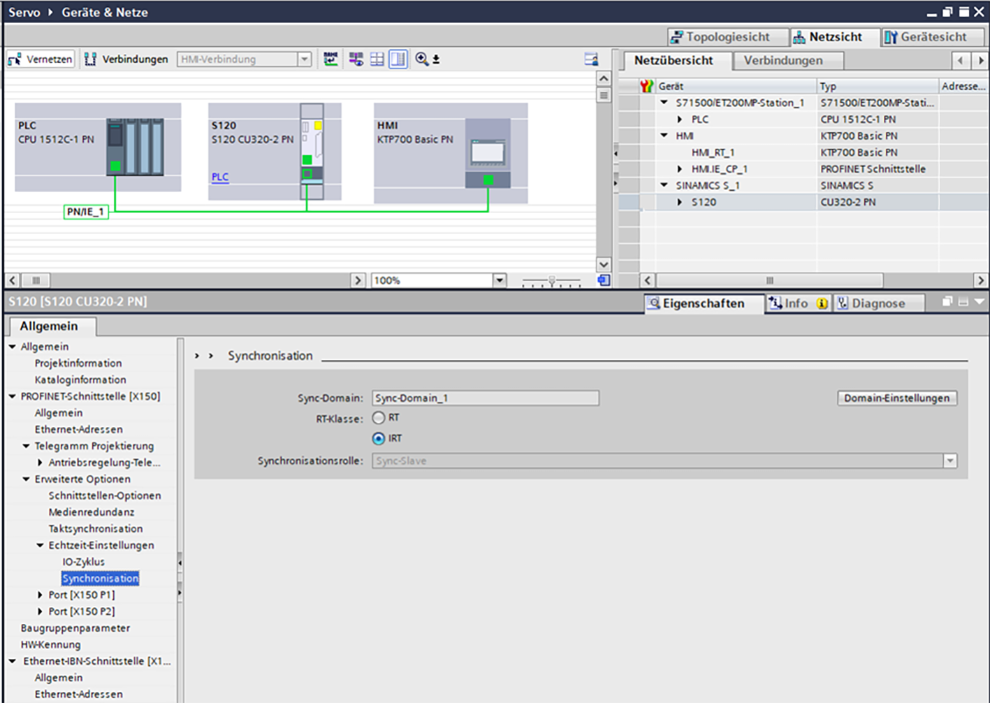
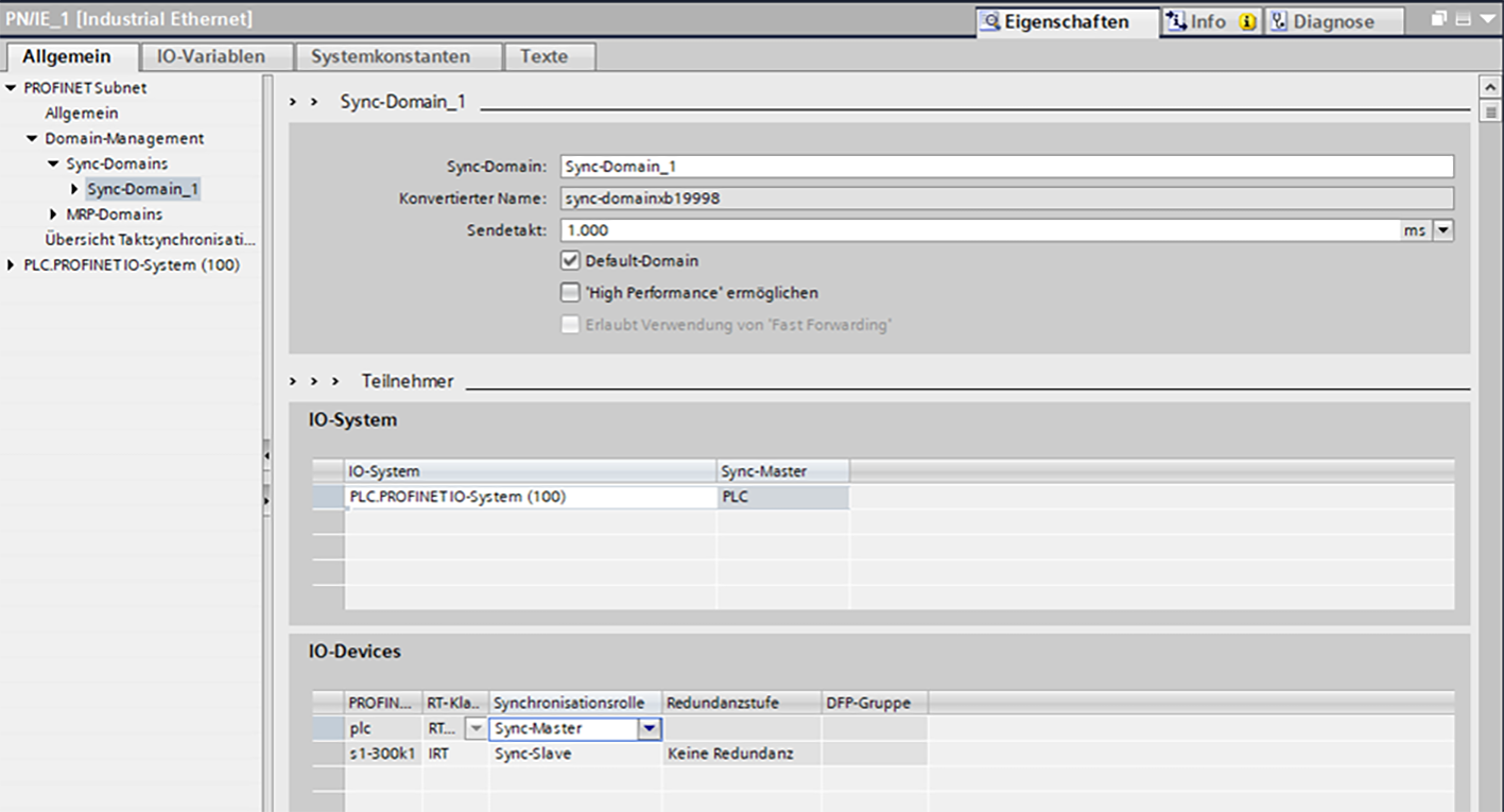
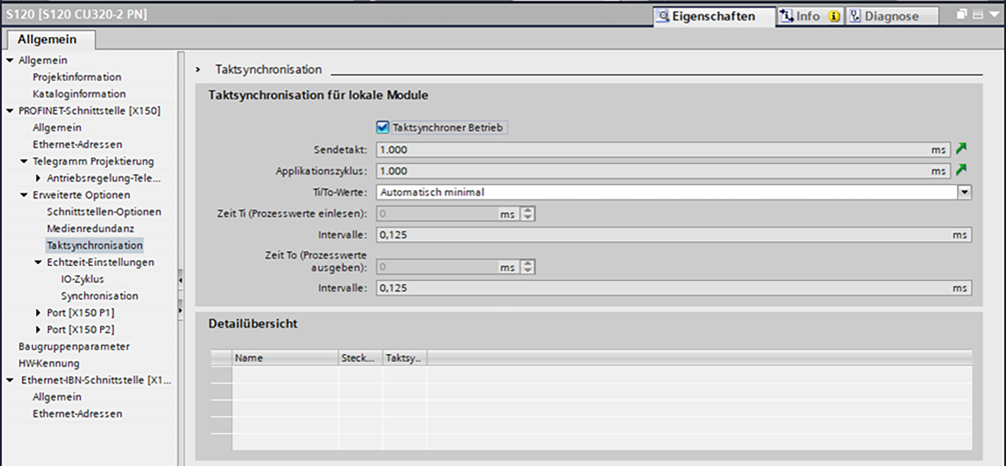
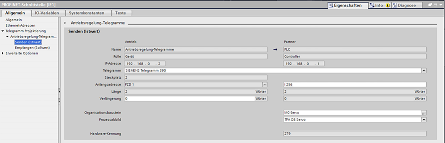
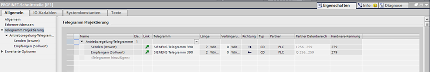
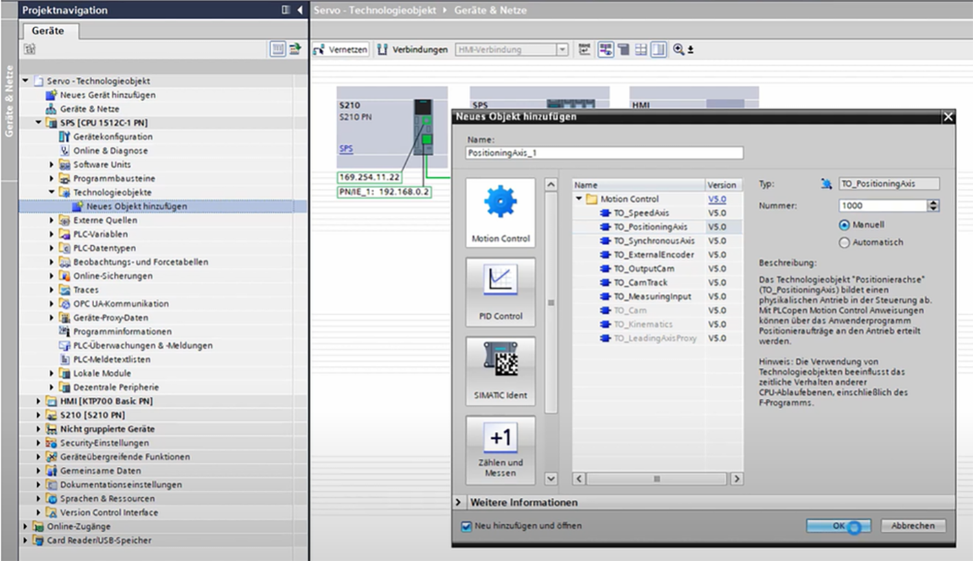
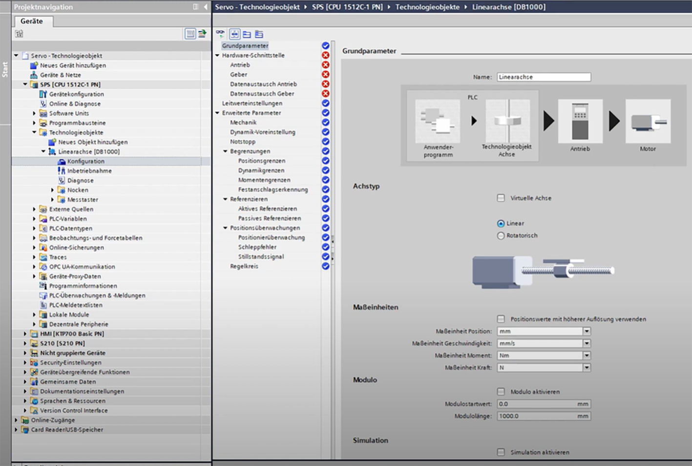
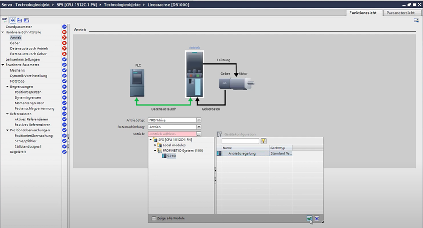
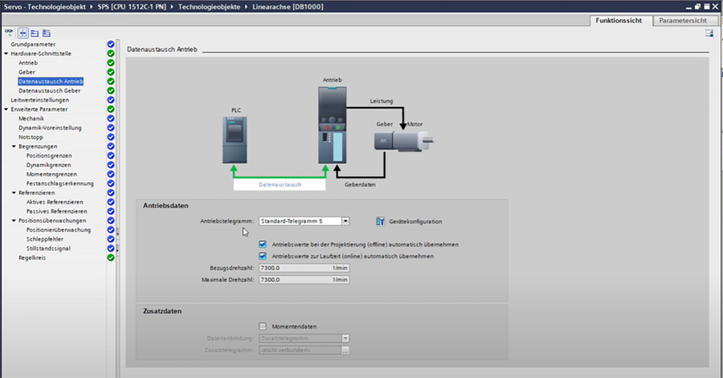
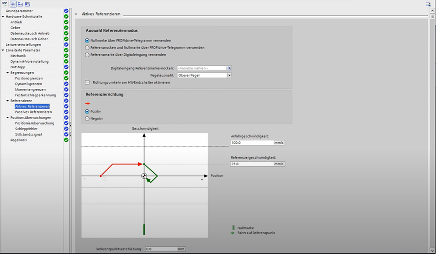
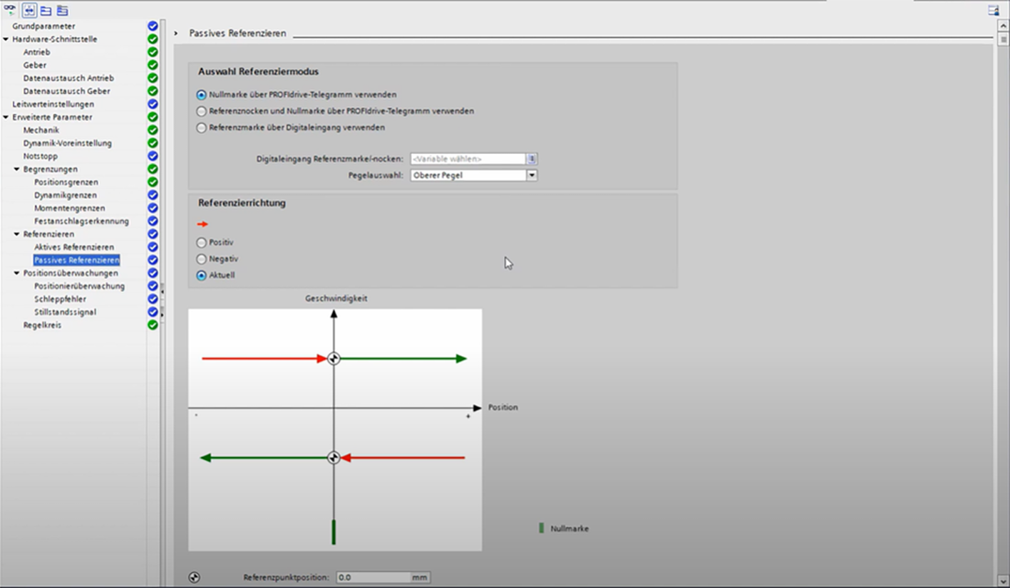
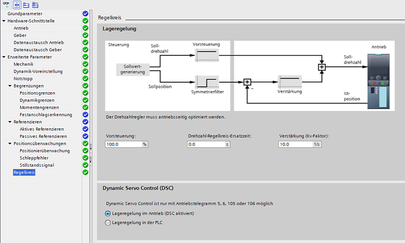
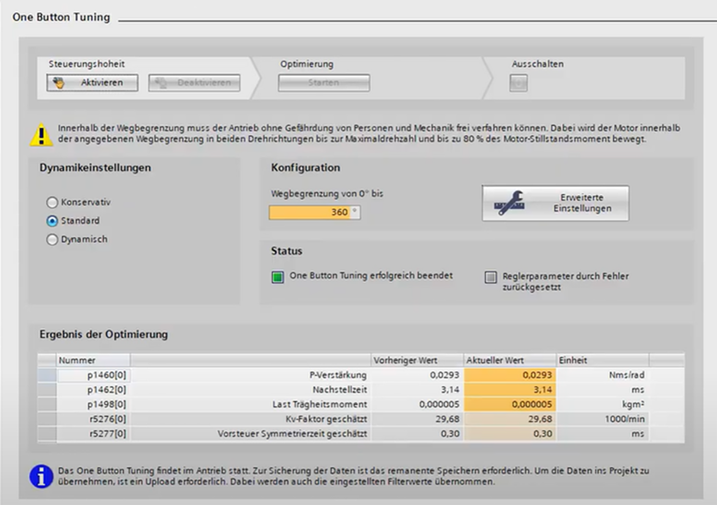
This article provides a structured guide for the initial commissioning of a drive system in Siemens TIA Portal using a technology object (TO). It covers the most important steps, from basic hardware configuration and network setup to parameterization, communication, and functional testing, ensuring a reliable and safe startup process.

It is particularly relevant for automation engineers and PLC programmers working with Siemens SINAMICS drives. However, it does not replace the need for deeper knowledge of motion control principles as incorrect parametrization can lead to unsafe machine behavior, mechanical damage, or personal injury.

Guide

1. We check under 'Online Access' whether all participants can be reached. The symbols make it easy to identify which device is a drive

2. Assign an IP address to SINAMICS. All subscribers must be within the same IP range and subnet. The exact IP address can be found in the EPlan or the documentation.

If the servo drive has been used elsewhere, it is advisable to reset it to its factory settings.

3. In Diagnostics > General, we can find information about the controller, such as the article number and firmware version. The firmware of the inserted Compact Flash (CF) card must match the version currently released by the standard team.

4. We insert our SINAMICS S120 in the hardware configuration via the hardware catalogue.

5. The device appears in the network view. We then adjust the IP address and device name before connecting the device to the network.

The second interface of SINAMICS is intended for our PG (programming device). This allows us to put the drive into operation, e.g. via a web browser.

6. Read out motor and encoder data (DRIVE CLiQ technology) using "Device Configuration Detection".

Restarting the device may be helpful if you experience any problems.

Components without an electronic type slot (not DRIVE CLiQ) must be inserted and specified from the hardware catalogue.

7. Check the device configuration in the device view. Then save the project and load the configuration into the drive unit.

If the topology in the hardware configuration (HW config) differs from the physical topology, you will receive an error message and the differences will also be shown in the HW config. In this case, you should correct the topology in TIA Portal or on the device itself.

8. The properties contain the data about the motor and the encoder.

9. Save everything and load the configuration onto the drive.

10. We can connect online to the drive to test the function. Go to "Commissioning" of an axle and then to the "Control panel".

Activate the control authority and read the warnings at least once. Keep checking the online status and make sure it is active! Releases are set from the PG. Set a very low speed to avoid damaging the mechanics, then start the axle.

Tap mode: The axis runs while you hold down the mouse button

The control panel is only active for a single object at a time. It also provides a quick diagnostic overview and the chance to acknowledge errors. It is for testing purposes only!

11. In the network view, set the communication to IRT (Isochronous Real-Time). This requires a topology. Here, we need to determine how the participants are wired.

12. In the network view, we access the properties of the Profinet port of SINAMICS. Under Advanced Options > Real-time settings > Synchronisation, we enable IRT. SINAMICS is the sync slave and the CPU is the sync master.

We define the sync master under "Domain management".

Isochronous operation must still be activated for SINAMICS.

13. The PLC and SINAMICS communicate via telegrams. Open the device configuration of the drive object, then the properties of the PROFINET (PN) interface. Select a telegram for the axis. Change the input and output addresses based on the default settings. For isochronous operation, add an organization module.

Write down the assigned hardware identifiers for the standard telegrams. Then save the project.

14. Create a new technology object for a positioning axis.

Every configuration action happens offline! Save in the project, then download it to the drive unit. Next, adjust the absolute encoder (RAM >ROM), upload to the project and save in the project.

15. In the configuration, we enter a suitable name and adjust the basic parameters of the axis.

16. In the hardware interface, we select our drive.

17. All other data was transferred automatically to TO from the HW configuration and parameterisation of the drive

18. Under "Mechanics", you can determine how the encoder was mounted and calculate the spindle pitch if this information is not included in the datasheet. If necessary, define the gear ratio (integer).

19. Under "Dynamic default values" you can set the desired target speed, acceleration, start-up time and return time. Initially, select a conservative value to protect the mechanics. If necessary, these parameters can be specified via a PLC Open module.

20. Activate the software limit switch.

21. In the "Moment limits", limit the moment of the axis, if included and needed in the telegram.

22. In the 'Homing' tab, reference the axis either actively or passively, depending on the application.

23. Depending on the application, determine the position monitoring, following errors and standstill signal.

24. In the "Control loop" tab, you can determine whether the position control takes place in the drive or the PLC.

25. With "One Button Tuning," you can determine the optimal control parameter for the SERVO drive. Activate control sovereignty. To do so, stop the CPU and ensure that the drive is error-free. Then, select the ideal dynamic settings and possible distance limitations. After optimization, reload the project into the drive.

26. Test the positioning using the control panel. If the motor rotation direction needs to be changed, proceed as follows:

  • p10 from 0 (ready) to 3 (motor IBN)

  • p1821 from 0->1 or from 1->0

  • Set p10 back to 0 (ready)

A new drive referencing process is required.