TwinCAT Vision is an integrated image processing solution of Beckhoff. Instead of handling vision sensors outside of the runtime environment of the PLC as a fieldbus slave, with TwinCAT Vision it is possible to handle all vision sensors with real-time tracing, which is a big advantage. What could be a disadvantage? Of course, the source you need to acquire these images and process them. Images are tons of data and in this case, PLC needs to hold this data in memory until the processing ends. Therefore, you will need to spare much source from your PLC for image processing. Without using TwinCAT Vision, the vision sensor acquires the image, processes it with its own memory and processor and sends only the necessary data (such as results, user defined data, status etc.). This can be achieved with max. 100 bytes of data.
1 System Components
TwinCAT Vision is a system component just like the other TwinCAT engineering environment based on visual studio. So how does this system work and what does it use? Let’s find out before moving on to hardware configuration.

1.1 Configuration Assistants
- Industrial cameras can be connected via the GigE Vision interface. Assistants are available for configuration, calibration, and simulation of the cameras. GigE Vision is an interface standard for industrial image processing, which uses gigabit Ethernet communication protocol. Assistants are similar to setup wizards for easier configuration, calibration, etc. for cameras connected via GigE vision. This will be explained later.
- Images can be loaded to the PLC runtime via a File Source element, instead of getting the images from the camera directly on run time. This may be useful for fine-tuning or the development of a camera application with tons of images that are saved on an external storage.
- It is needed to make the configuration of cores and router memory for TwinCAT Vision via TwinCAT real-time settings.
- Vision Job Pool can be used to execute some algorithms in parallel on a different core.
1.2 PLC Library
There is a library for TwinCAT Vision, which provides a large number of algorithms for image processing, function blocks and functions for the communication with the file system and interface of the cameras. The programming of the application will not be covered here. More information can be found at API reference.
1.3 Debugging Tools
- ADS Image Watch: It is a tool that allows you to monitor the captured image in a development environment. Normally the PLC receives images with a different interface to process it. ADS Image Watch receives the image with a displayable interface. However, it is not possible to do image processing in this format.
- ADS Return Codes: Each TwinCAT Function provides information about its execution status via ADS Return Codes. These can be used for debugging.
- In addition, all debugging tools (breakpoints etc.) can also be used for image processing programming.
1.4 GigE Vision Driver
GigE Vision Driver is the driver of TwinCAT to communicate with industrial cameras based on GigE Vision standards.
1.5 TwinCAT Vision Service
The TwinCAT Vision Service is a centralized, ADS-based communication interface between the TwinCAT runtime and external Vision components. If some functionalities are needed that require TwinCAT Vision to communicate with components outside of the real-time environment at runtime (i.e. File Source Control loads image from the file system), this communication interface needs to be used.
2 Installation
2.1 System Requirements
2.1.1 IPC Hardware
| Technical data | Description |
| TwinCAT 3 Platform-Level | Minimum P50 Performance Plus, e.g. Intel 4-core Atom CPU |
| Network adapter |
TwinCAT real-time Ethernet-compatible Gigabit network cards (for connecting GigE Vision cameras)
Note: At least one network port should be available exclusively for cameras. It is recommended to use a separate network port for each camera. |
| Main memory |
Minimum 4 GB recommended for pure runtime systems
Minimum 8 GB recommended for development systems
Minimum 8 GB recommended for the use of record/playback streams on runtime systems |
| Hard disk | SSD hard disks with high reading/writing rates are recommended, especially if a lot of data is to be exchanged between PLC and hard disk. |
2.1.2 Camera
| Technical data | Description |
| Interface |
Must support GigE Vision. (marked with GigE Vision logo)
Note: The TwinCAT GigE Vision Connector is certified according to the GigE Vision Standard version 2.0. However, this does not mean that all camera or GigE Vision features of the version are supported. |
2.1.3 Software
| Technical data | Description |
| Operating system | Windows 7 or 10 (64-bit only!) |
| Supported Visual Studio versions |
2017 (Community, Professional)
2019 (Community, Professional)
TwinCAT XAE Shell (TcXaeShell) |
| TwinCAT | Minimum version 3.1.4024.17 |
| .NET Framework | Minimal version 4.6.1 (only for the development environment) |
2.1.4 Setup Instructions
Just follow the instructions from Setup Instructions for TwinCAT Vision and do not forget the Licensing.
3 Building Environment
After a successful installation, we will start with creating a project and do the basic settings like real-time settings.
It is recommended to use isolated cores for TwinCAT Vision applications. It is OK to use shared cores for initial testing but, as mentioned at the beginning of the blog, image processing requires a lot of resource.
Configure the router memory according to the application. Note that images require high router memory but on the other hand this memory you allocated will be subtracted from RAM. Consider checking the required memory size and be sure, there is enough memory for the rest of the applications.
Default stack size probably not enough for image processing. It is recommended to increase the stack size 512 Kb minimum.
3.1 Create a Vision Device
Now we can set up a vision application. To be able to see the vision tool, we need to unhide it.
Step 1:
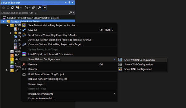
Right-click the TwinCAT project in the Solution Explorer > Show Hidden Configurations > Show VISION Configuration.
Step 2:
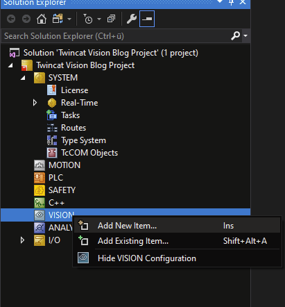
Now its visible, right click on it and add new application.
Step 3:
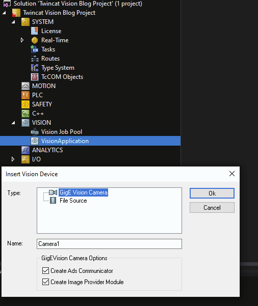
Right click on the icon with your application name and select “add new item”. After that, you see the windows below. Now we can add either a real camera or a file source where we get images from a folder.
Step 4:
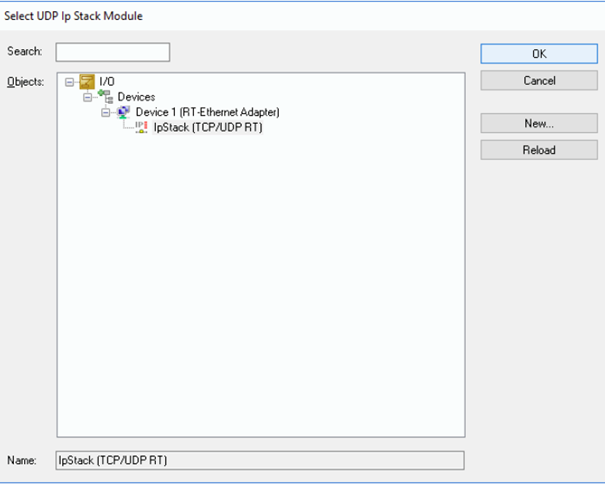
Select GigE vision camera from step 3 and click OK. A window will open which requires us to choose the ethernet port with which the camera is connected.
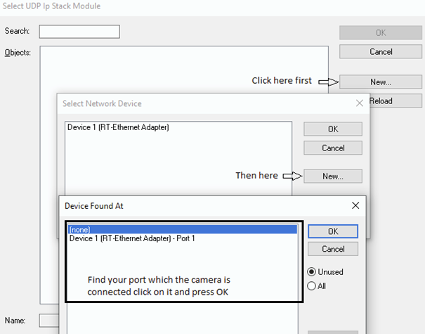
Select IPStack and click OK.
Step 5:
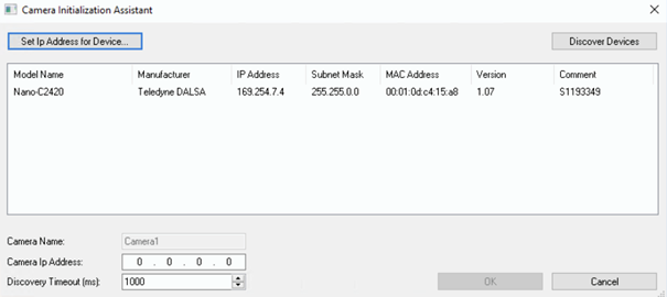
Click discover devices and select the camera that you want to connect to the vision object and click OK.
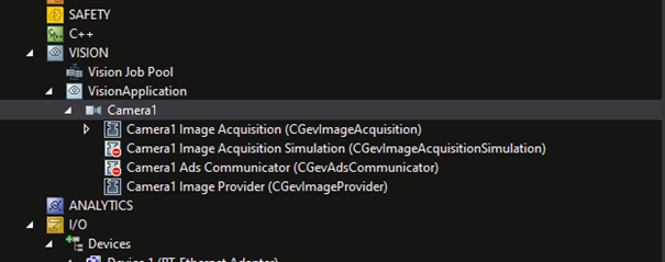
Now the camera can be seen under the vision application.
Double click on the camera node and the following page will open. We can monitor the general information and the status of the camera in the “General” section.
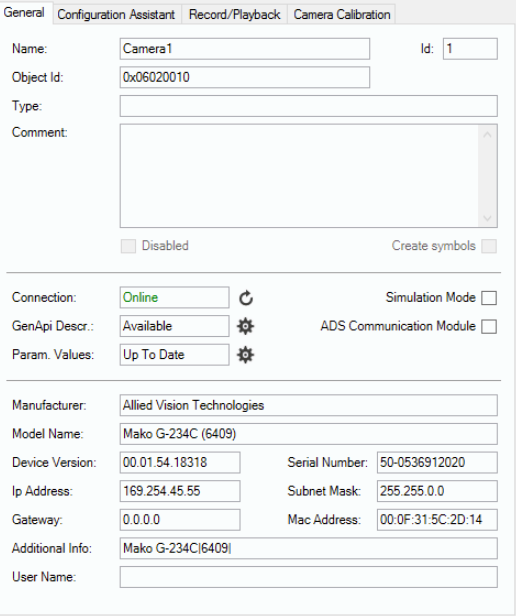
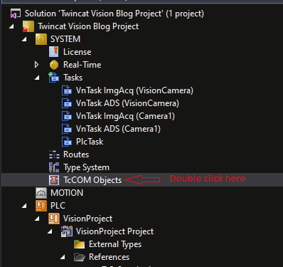
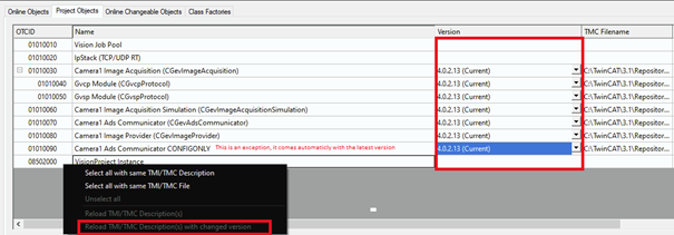
It is very important to use the same TwinCAT Vision version for all TcCOM objects. If you are using a spesific version, check and confirm all of your TcCOM objects are of the same version. To check and update the versions, see the window below.
3.2 Ethernet Adapter Settings
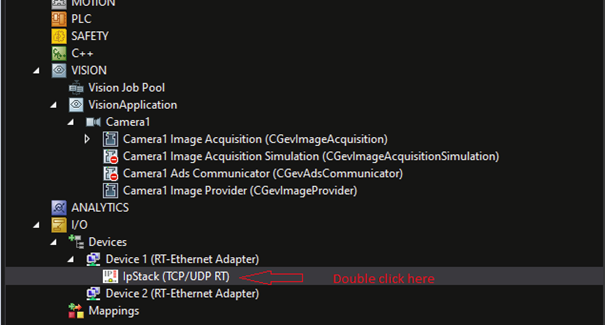
- Open the IP-Stack of the RT-Ethernet adapter in the I/O configuration.
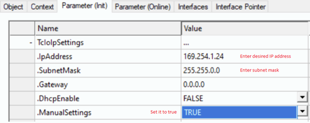
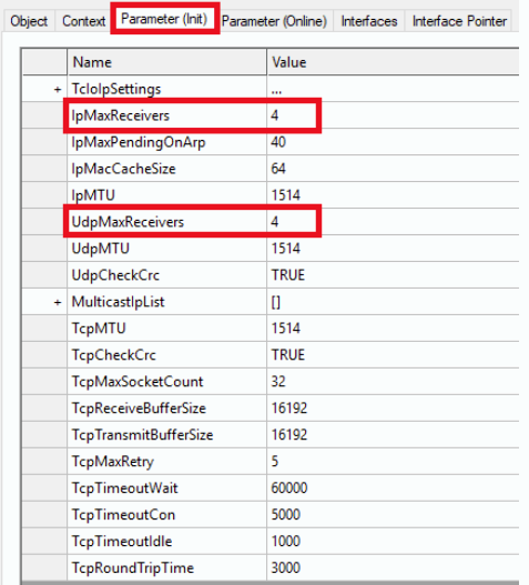
- Select the Parameter (Init) tab and display further parameters by clicking the Plus (+) in front of TcIoIpSettings.
- Define the parameters
.IpAddressand.SubnetMask - Set the parameter
.ManualSettingsto TRUE.
If you want to add multiple cameras in one port (it is not recommended by Beckhoff, but I think it will be needed) set the parameters below. The formular is camera quantity*2 (i.e if you have 3 cameras on port these will be 6 ).
Make sure that “Promiscuous Mode” for vision ports is deactivated. It may lead to problems when communicating with GigE Vision devices.
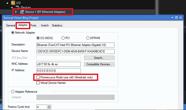
Promiscuous Mode Setting. Under I/O section
3.3 Vision Node Settings
3.3.1 Service Configuration
TwinCAT Vision Service is a bridge between non-real-time components and real-time components. For example, if you want to save an image that you have in real-time at runtime on a non-real-time disk, TwinCAT Vision Service implements an ADS server to access both and enables communication.
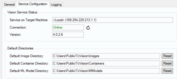
Do not forget to make the install TwinCAT Vision Service.
4 Create PLC Project
Now let’s create a standard PLC project and add TwinCAT vision libraries.
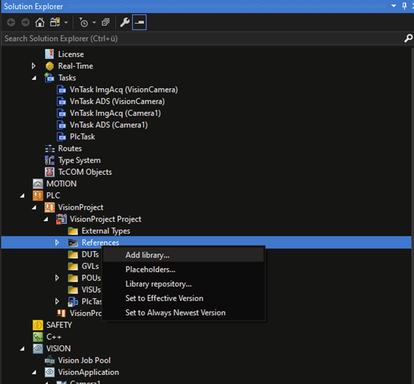
Click Add Library.
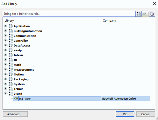
Click Tc3_Vision and OK.
Then instantiate a FB with a library that we just installed.

We need to connect that FB, which we will use to manage the camera, to the image provider. To do that build the project, go to PLC instance tab and click the Symbol Initialization section.
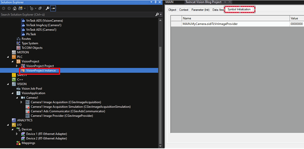
Here you can see the camera name that we instantiated. Click on the “Value” drop-down and link the symbol with the camera that we created.

Now activate the configuration.
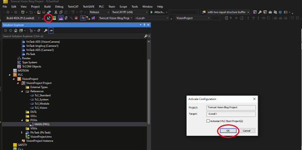
Now we have a camera that is connected to our PLC and linked to TwinCAT. It can be used by TwinCAT Vision Libraries.
